 Info Tool
Use this tool to get information on items in your design.
To select this tool, click on the Info Tool button in the tool palette. When you do, a floating window appears as shown below.
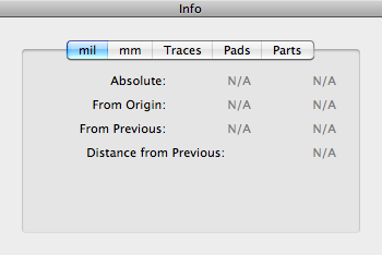
Now when you click on a feature, such as a pad or a vertex of a trace, the position information is shown in the information window like this.

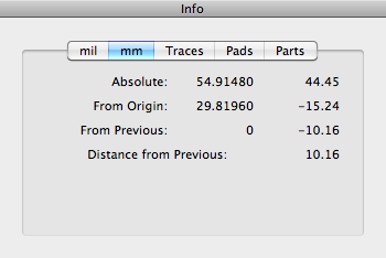
The Absolute position (X and Y coordinates) is with respect to the lower left-hand corner of the design area. The From Origin position is relative to the grid origin. The grid origin can be changed using the Origin tool described elsewhere. The From Previous position is relative to the last item you clicked. The Distance from Previous field shows you the straight line distance from the last item you clicked. All numbers are in unit of mils.
If you would prefer to see the position in Metric units, click on the mm tab to see something like this.
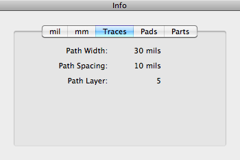
By clicking on the Traces tab, you can now get information about all visible traces, including width, spacing, and layer, like this.
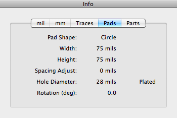
Clicking the Pads tab allows you to get information on pads.
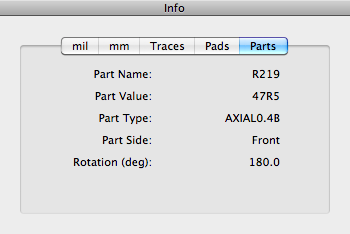
Finally, clicking the Parts tab allows you to get information on parts.
 Origin Tool
Use this tool to move the origin or index point of the grid.
To select this tool, click on the Origin Tool button in the tool palette or press the I key on the keyboard.
To use the tool, click on a visible pad or vertex. The index point will move to the center of the pad or vertex you clicked, even if the pad or vertex is not on a grid location.
 The index indicator (which looks like this) will appear at the new index point and the grid will be redrawn so that the new index point is the origin of the grid.
If you click on a point that is not near a pad or a peg, the index point will snap to the grid location nearest the point you clicked.
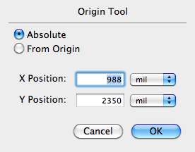
If you double-click the tool in the tool palette, the dialog as shown below appears. This dialog shows you the current position of the index point and lets you change it manually. Using the pull-down menu next to each edit field, you can specify the position in either mils or millimeters.
 Draw Tool
Use this tool to draw freehand paths. Options allow you to draw straight lines, rectangles and ovals.
To select this tool, click on the Draw Tool button on the tool palette.
To use this tool, click the mouse at one point and drag to a second point. As you are dragging, a "ghost" line (or rectangle, or oval) will stretch like a rubber band to show your path. When you release the drag, a new freehand path (or rectangle, or oval) will be drawn. The path width and spacing are defined by the current tool values.
If you are drawing a straight path and the first or second point coincide with a vertex of an already existing freehand path, and that vertex has no more than two paths (i.e, it is not already a "Y"), the new path will become attached to the old path.
If you are drawing a straight path and the Ctrl key is pressed, the angle of the line drawn by the tool will be constrained to an integral multiple of 45 degrees. If you are drawing a rectangle and the Ctrl key is pressed, the result will be either a straight path or a square. Similarly if you are drawing an oval, the Ctrl key will produce either a straight path or a circle.
To change the drawing mode or to modify the current tool values, double-click on the Draw Tool button on the tool palette to bring up the dialog as shown below.
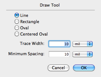
In Line mode, a straight path is drawn from the click point to the drag point. In Rectangle mode, a rectangle is drawn with the corners defined by the click point and the drag point. Similarly, in Oval mode, an oval is drawn with the corners of the imaginary enclosing rectangle defined by the click point and the drag point. In Centered Oval mode, the center of the oval is defined by the click point and the extent of the oval is defined by the drag point.
![]() If you hold down the shift key, the cursor will change to this icon to indicate that you are now in sample mode. If you click on any path while in sample mode, the current tool values will change to that of the clicked path. This is very useful if you wish to make the new path the same width and spacing as some other path.
If you hold down the shift key, the cursor will change to this icon to indicate that you are now in sample mode. If you click on any path while in sample mode, the current tool values will change to that of the clicked path. This is very useful if you wish to make the new path the same width and spacing as some other path.
 Text Tool
Use this tool to create text-like parts.
To select this tool, click on the Text Tool button on the tool palette.
To use the tool, you should first configure it by double-clicking on the Text Tool button on the tool palette to bring up the dialog below.
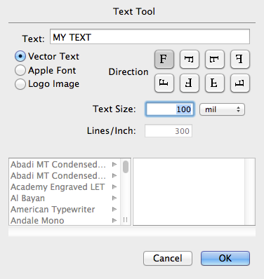
The dialog lets you select the text direction including horizontal and vertical directions, both normal and mirrored, as indicated by the orientation of the F character in the selection buttons. You must enter the desired text string and select the size of the text in either mils, millimeters, or points.
If you set the Vector Text button, the text part will be created using vector character definitions from your library. However, if you set the Apple Font button, the dialog changes to allow you to use any available Apple Font to create text parts.
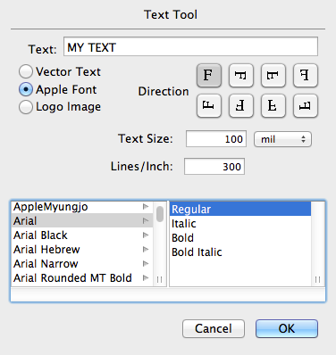
Text parts made from Apple fonts are created using a series of closely spaced horizontal, vertical, and diagonal lines in a raster pattern. Obviously, as you increase the density of lines (lines per inch), the text will more closely approximate the actual font outline. You can select the number of lines per inch used in this raster pattern by changing the number in the Lines/Inch field. Higher numbers will result in better looking text but also greater memory usage.
Once the tool is configured, click on any point on any layer. A text-like part consisting of the desired text string will be created and placed at the clicked location, with the origin of the part snapped to nearest grid location.
![]() If you hold down the shift key, the cursor will change to this icon to indicate that you are now in sample mode. If you click on any text part while in sample mode, the current tool values will change to that of the clicked text part. This is very useful if you wish to make a new text part similar to an already existing one.
If you hold down the shift key, the cursor will change to this icon to indicate that you are now in sample mode. If you click on any text part while in sample mode, the current tool values will change to that of the clicked text part. This is very useful if you wish to make a new text part similar to an already existing one.
If you hold down the option button while clicking on an existing text part, the above dialog appears with the current tool values changed to those of the text part you clicked. Modifying the values (including the text string itself) and pressing the OK button then changes the text part accordingly.
If you set the Logo Image button, the dialog changes to allow you to place a logo image on the design. The mechanism used to render the logo image is similar to the method used to render text with Apple fonts, that is, by using a series of closely spaced horizontal, vertical, and diagonal line segments. You can use the Text Size field to change the height of the logo image and the Lines/Inch field to change the line spacing.
By default, the Osmond logo image is used, but the image can be changed by importing a new image with the
Import → Logo Image…
command from the File menu.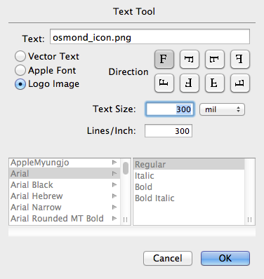
 Curve Tool
Use this tool to change a sharp path corner into a rounded path as shown in the before and after pictures below.


To select the tool, click on the Curve Tool button on the tool palette.
To use the tool, click on the vertex of a path where a corner exists. This vertex should not be part of a "Y". The corner will be transformed into a round path with radius equal to the tool default radius.
To change the current tool radius, double-click the Curve Tool button on the tool palette to bring up the dialog below.
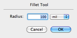
Using the pull-down menu next to the edit field, you can specify the radius in either mils or millimeters.
 Change Pad Tool
Use this tool to change the shape and size of a pad.
To select this tool, click on the Change Pad tool button on the tool palette.
To use this tool, click on a pad to change it to the current tool values.
![]() If you hold down the Command key, the cursor changes to this. Now if you click on a pad, it is changed to the current tool value rotated 90 degrees.
If you hold down the Command key, the cursor changes to this. Now if you click on a pad, it is changed to the current tool value rotated 90 degrees.
To modify the current tool values, double-click on the Change Pad tool button on the tool palette to bring up the dialog shown below. For the moment, lets ignore the Dual Pad button and look at the fields that let you define a regular pad.
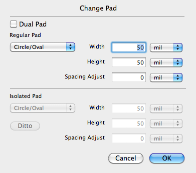
A pop-up menu lets you specify the shape of the pad. The values are as follows:
- Circle/Oval
- Square/Rectangle
- Hex-Oval
Whether a pad is a circle rather than an oval (or a square rather than a rectangle) depends, of course, on the width and the height.
A Hex-Oval shape is very similar to a regular oval shape. The only difference is in the way paths are routed around the pad. Paths route around a regular oval pad as if it were an octagon. This produces a routing pattern like this.
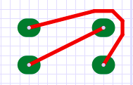
On the other hand, paths route around a Hex-Oval pad as if it were a hexagon. This produces a routing pattern as shown below. This routing pattern may be preferable when we have an alternating offset or zig-zag arrangement of pads.

The Width and Height fields in the dialog allow you to determine the size of the actual pad itself.
The pull-down menu next to each edit field lets you specify the width and height of the pad in either mils or millimeters.
Paths generally route around pads based on the shape and size of the pad, and the width and minimum spacing of the path. For example, lets construct the following scenario:
- Circular pad
- Pad Width = Pad Height = 75 mils
- Path Width = 15 mils
- Path Minimum Spacing = 10 mils
In this scenario, to maintain the correct spacing, the center of the path must be at least 55 mils away from the center of the pad (75/2 + 15/2 + 10 = 55).
The Spacing Adjust field in the dialog lets you modify the amount of spacing that the system provides for this pad. For example, if we add the following item to the above scenario:
- Spacing Adjust = 5 mils
Then, to maintain the correct spacing, the center of the path must now be at least 60 mils away from the center of the pad (75/2 + 15/2 + 10 + 5 = 60).
The Spacing Adjust field can be a positive number if you wish to provide additional spacing around a pad, or it can be a negative number if you wish to allow paths to approach the pad more closely than they would otherwise be allowed.
Dual Pad
In the Osmond system, a pad can have a different shape and size depending on whether it is connected or isolated. This is called a Dual Pad. Connected means that the pad has at least one connecting path, while isolated means that the pad has no connecting path. When a pad is changed from isolated to connected (by adding a connecting path), the shape and size of the pad changes automatically from the isolated pad shape and size to the connected pad shape and size, and vice versa.
This ability to automatically change pad shape and size depending on whether the pad is or is not connected has proven valuable in routing inner layers. A through-hole pin generally does not need a large pad on an inner layer if there is no connection on that layer. All it needs is sufficient area for a plated through hole which can be much smaller than the area needed for a pad. If a connection is needed on the inner layer, however, then a larger pad should be used. This ability can therefore increase the available area on inner layers which may make routing much easier.
Clicking on the Dual Pad check-box changes the dialog to look like this.
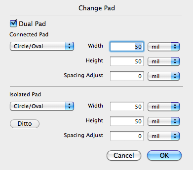
You specify the shape and size of the connected pad in the upper area and specify the size and shape of the isolated pad in the lower area. The Ditto button is a short cut to copy the connected pad settings to the isolated pad settings.
If you hold down the option button while clicking, the above dialog will appear with the current tool values changed to those of the pad you clicked. Modifying the values and pressing the OK button will then change the pad accordingly.
![]() If you hold down the shift button, the cursor will change to this icon to indicate that you are now in sample mode. If you click on any pad while in sample mode, the current tool values will change to that of the clicked pad. This is very useful if you wish to make one pad the same as another pad; you simply sample one pad and then click on the other.
If you hold down the shift button, the cursor will change to this icon to indicate that you are now in sample mode. If you click on any pad while in sample mode, the current tool values will change to that of the clicked pad. This is very useful if you wish to make one pad the same as another pad; you simply sample one pad and then click on the other.
 Change Pin Tool
Use this tool to change a pin, which consists of the pin hole and all the pads in the padstack.
To select this tool, click on the Change Pin Tool button on the tool palette.
To use this tool, click on a pad to change the associated pin to the current tool values.
![]() If you hold down the Command key, the cursor changes to this. Now if you click on a pin, it is changed to the current tool value rotated 90 degrees.
If you hold down the Command key, the cursor changes to this. Now if you click on a pin, it is changed to the current tool value rotated 90 degrees.
To modify the current tool values, double-click on the Change Pin Tool on the tool palette to bring up the dialog shown below. This dialog allows you to specify the hole size, whether or not the hole is plated, whether or not the pin has a solder mask cutout, and the shape and size of all the pads in the padstack.
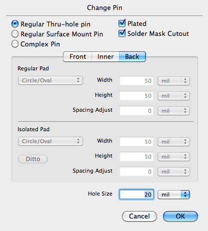
The dialog provides three radio buttons that let you specify if the padstack defines a regular thru-hole pin, a regular surface mount pin, or a complex pin. In a Regular Thru-hole pin, all pads on all layers are identical. For a Regular Surface Mount Pin, only the front pad is defined and there are no pads on the inner or back layers. In a Complex Pin, pads on different layers may be different or even non-existent.
The dialog also presents three panels labeled Front, Inner, and Back. If the Regular Thru-hole or Surface Mount button is selected, only the Front panel is enabled since the pads on the inner and back layers are either identical to the front pad (Regular Thru-hole pin) or non existent (Regular Surface Mount Pin). For a discussion of the fields in each of the panels, see the description of the Change Pad Tool.
In the Front, Inner, and Back panels, the popup menu allows you to choose the usual pad shapes plus the additional option of having no pad at all. You may use this option when creating a surface mount pin which has no pads on the inner or far side layer.
Using the pull-down menu next to each edit field, you can specify the width, height, or spacing adjust values in either mils or millimeters.
If you hold down the option button while clicking, the above dialog will appear with the current tool values changed to those of the pin you clicked. Modifying the values and pressing the OK button will then change the pin accordingly.
![]() If you hold down the shift button, the cursor will change to this icon to indicate that you are now in sample mode. If you click on any pin while in sample mode, the current tool values will change to that of the clicked pin. This is very useful if you wish to make one pin the same as another pin; you simply sample one pin and then click on the other.
If you hold down the shift button, the cursor will change to this icon to indicate that you are now in sample mode. If you click on any pin while in sample mode, the current tool values will change to that of the clicked pin. This is very useful if you wish to make one pin the same as another pin; you simply sample one pin and then click on the other.
 New Pin Tool
Use this tool to create a new pin which may later be combined with other pins and paths to create a new part.
To select this tool, click on the New Pin Tool button on the tool palette.
To use this tool, click anywhere in the design view. A new pin is created according to the current tool values and placed at the nearest grid location.
![]() If you hold down the Command key, the cursor changes to this. Now if you click anywhere in the design view, a new pin is created from the current tool values, only rotated 90 degrees.
If you hold down the Command key, the cursor changes to this. Now if you click anywhere in the design view, a new pin is created from the current tool values, only rotated 90 degrees.
To modify the current tool values, double-click on the New Pin Tool button on the tool palette to bring up the dialog shown below.
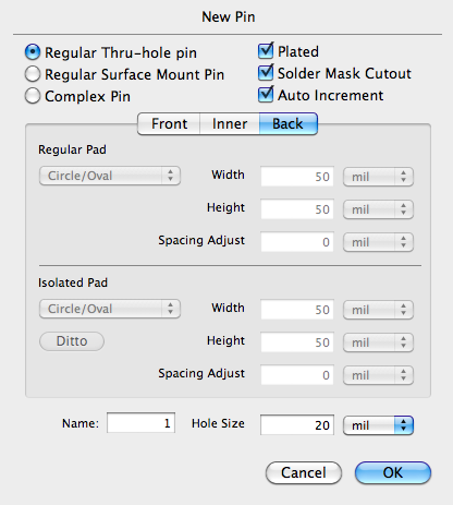
This dialog is very similar to dialog used by the Change Pin tool described above. The only additions are the Name field and the Auto Increment checkbox. The name field lets you specify the name of the next pin created. If the Auto Increment button is checked, then subsequent pins will have new names that increment numerically.
For example, if you specify 1 in the name field, the next pin created will be named: 1. The next pin after that will be named: 2, and the next pin after that will be named: 3, and so on.
Pins created with this tool are in reality, individual parts containing a single pin. As such, they can be manipulated with all the tools used to manipulate parts.
Using the pull-down menu next to each edit field, you can specify the width, height, or spacing adjust values in either mils or millimeters.
![]() If you hold down the shift button, the cursor will change to this icon to indicate that you are now in sample mode. If you click on any pin while in sample mode, the current tool values will change to that of the clicked pin. This is very useful if you wish to make the new pin the same as another pin; you simply sample the pin and then click at a new location to create the new pin.
If you hold down the shift button, the cursor will change to this icon to indicate that you are now in sample mode. If you click on any pin while in sample mode, the current tool values will change to that of the clicked pin. This is very useful if you wish to make the new pin the same as another pin; you simply sample the pin and then click at a new location to create the new pin.
 Thermal Tool
Use this tool (also called the Surround Tool) to adjust the thermal and void pads on a ground or signal plane. Within a copper flood area, this tool also allows pads to connect into the copper flood itself.
To select this tool, click on the Thermal Tool button on the tool palette.
A common method of forming a ground or signal plane is by etching the copper on a PC board layer with a reverse image instead of a normal image. Using a normal image, paths and pads show where the copper remains; but using a reverse image, the paths and pads show where the copper is removed.
On a signal plane layer, Osmond can use patterns of reverse image pads and paths to control whether or not a pin is connected to the ground or signal plane. In the illustration below, the reddish area shows where copper remains on the layer while the white area shows where copper is removed from the layer. Gray circles show where there is a hole for a through-hole pin.

In the first pattern, a reverse image pad (called a void pad) removes the copper from around the through-hole pin. This causes the pin to be completely isolated from the copper plane.
In the second pattern, eight reverse image paths surround the hole leaving an area of copper in an octagon shaped annular ring. The pin connects to the copper in the annular ring but is still isolated from the copper plane.
The third pattern is like the second except two of the surrounding paths have been removed. Now, the pin is connected to the copper in the annular ring and also connected to the copper plane through passages on the left and right hand side of the pin. If we were to remove all the surrounding paths, the pin would still be connected to the copper plane but soldering the pin would be more difficult because of the large heat sink provided by the copper. The surrounding paths therefore act as thermal barriers to permit easier soldering.
The fourth pattern is similar to the third except two different surrounding paths have been removed to provide diagonal connecting passages to the copper plane.
To use this tool to change the reverse image pattern around a pin, click on a pad on a ground or signal plane layer. The pad changes according to the current tool values.
To change the current tool values, double-click on the Thermal Tool button on the tool palette to bring up the dialog shown below.
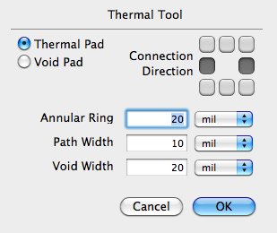
The dialog has two radio button that let you select if the reverse image pattern is a Thermal Pad (consisting of surrounding paths) or a Void Pad.
If the pattern is a Thermal Pad, the buttons to the right allow you to select which (if any) of the surrounding pads should be removed to create a connecting passage. The Annular Ring text field lets you specify the minimum width of the copper surrounding the hole, and the Path Width text field lets you specify the width of the surrounding reverse image paths.
If the pattern is a Void Pad, the Void Width text field lets you specify the minimum width of the copper-free ring surrounding the hole.
If you hold down the option button while clicking, the dialog above will appear with the current tool values changed to those of the pattern you clicked. Modifying the values and pressing the OK button will then change the pattern accordingly.
![]() If you hold down the shift button, the cursor will change to this icon to indicate that you are now in sample mode. If you click on any pattern while in sample mode, the current tool values will change to that of the clicked pattern. This is very useful if you wish to make one pattern the same as another pattern; you simply sample the pattern at one pin and then click on the other pin.
If you hold down the shift button, the cursor will change to this icon to indicate that you are now in sample mode. If you click on any pattern while in sample mode, the current tool values will change to that of the clicked pattern. This is very useful if you wish to make one pattern the same as another pattern; you simply sample the pattern at one pin and then click on the other pin.
The Thermal Tool can also be used to connect pads to a ground or power plane within a copper flood region. In a signal plane layer, the isolation is created by drawing surrounding reverse-image paths, and connections are made by removing one or more of these paths. In a copper flood region, on the other hand, the isolation around pads already exists and so connections are made by drawing one or more paths from the pad into the copper flood area. When you use the Thermal Tool on a pad that is not in a signal plane, short paths are automatically drawn from the pad out to where the edge of copper flood should be (even if there is no copper flood there).
 Check Tool
Use this tool to check the clearance of a path.
To select this tool, click on the Check Tool button on the tool palette.
To use the tool, click on a connecting path. The path is checked for clearance conflicts and if a conflict is found, the part of the path that has the conflict will be highlighted the dialog in Figure~\ref{f:checktool} will appear.
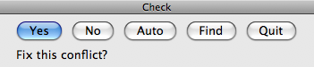
If you press No, the conflict will be skipped and the next conflict (if any) will be found and highlighted. If you press Quit, the check will be aborted and the dialog will disappear. If you press Auto, the Osmond system will attempt to resolve the conflict automatically by moving connecting paths without further dialog. If you press Yes, the Osmond system will attempt to find a solution to the conflict and will display that solution highlighted while changing the dialog as shown below.
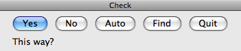
If you press Yes, the proposed solution will be implemented and the system will move on to the next conflict (if any). If you press No, the proposed solution will not be implemented and the system will attempt to find and present a different solution for your approval. If you press Auto, the proposed solution will be implemented and the system will attempt to resolve all remaining conflicts automatically without further dialog. If you press Quit, the proposed solution will not be implemented, the dialog will disappear, and all remaining checks will be aborted.
You can use keyboard shortcuts instead of pressing buttons to respond to the dialog as follows:
\begin{tabular}{ll} Yes & Y or return \\ No & N \\ Auto & A \\ Quit & Q or esc \end{tabular}
 Via Tool
Use this tool to place a via on the board. The tool works by creating a new VIA part and placing it on the board at the specified location. The via is added to the pin list of the current signal so you can immediately connect it to any other pin with the Connect tool.
To select this tool, click on the Via Tool button on the tool palette.
Before using this tool a signal should be selected. (You can select a signal by clicking on any pad belonging to that signal with the Connect tool.)
To use this tool, click on any location of the board. A new via is placed at the location you clicked, snapped to the nearest grid location.
If you have a part type defined in your library with the name "VIA", then that part type will be used. You can also select from a number of different via part types defined in your library. Part types should be given a name that begins with the three letters V, I, and A. You can use both upper and lower case. You could, for example, have via part types named "ViaLarge" or "VIA_VERSION2". To select which via type will be used, double click the Via Tool button. This brings up a dialog as shown below.
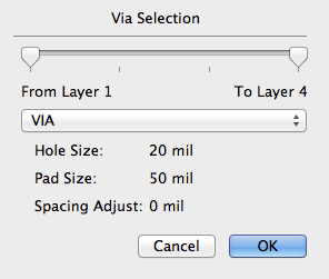
Use the pop-up menu to select by name which via type you wish to use. The text fields will give you information about the via type that was selected.
The two slider controls at the top of the dialog allow you to select which layers are affected by the via. Normally, the two sliders are set to the extreme left and the extreme right, meaning that the via extends all the way through the board, from the first layer (Layer 1) to the last layer (Layer 4 in the example). If you change one or both of the sliders, you can define a via that extends only part of the way through the board. Vias that extend from an outer layer to an inner layer are called blind vias. Vias that extend from an inner layer to another inner layer are called buried vias.
Blind or buried vias should be used with care. The indiscriminate use of blind and buried vias can easily result in a board design that cannot be fabricated. Currently, Osmond has no safeguards to prevent this.
If blind or buried vias are used, additional drill files and drill report files are generated when Gerber files are exported.
A via is a part like any other part. If you wish to remove a via, therefore, you can select it with the Select tool and then cut it or delete it.
 New Part Tool
Use this tool to create and place a new part on the board. The tool works in conjunction with the Library Parts window which contains lists of all part types in all open designs, either true designs or libraries. The popup menu allows you to switch among all open designs.
To select this tool, click on the New Part Tool button on the tool palette. The Library Parts floating window will become visible if it is not already so. This window looks like this.

Select a part type in the Library Parts window. A preview of the selected part appears in the preview pane. You may also specify the name of the part to be created in the text field.
Click and hold in the design area. A shadow of the new part appears where you clicked. Now you can drag this part to the desired location. Clicking again creates a new part. As each part is created, the numeric part of the Next Part ID is automatically incremented. However, if a part name is already being used, the numeric part of the Next Part ID will be incremented until the name is unique.