Building New Part Types
In this chapter we go through the process of building a new part type. We will build a simple imaginary part that will look like this:
Setup
Bring up the Osmond application if it not already running. Create a new design with the New command or open an existing design using the Open command.
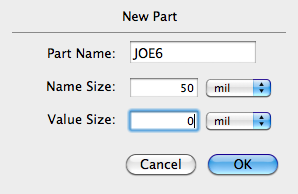
Now issue the Make New Part Type... command from the Parts menu. A dialog appears that allows you to name the new part type and to specify the height of the text to be used in the name field. Let us make a part type named JOE6 that has a name field height of 50 mils by entering the following in the dialog:
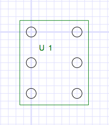
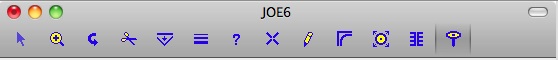
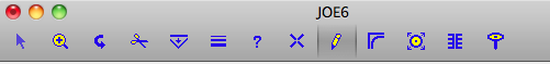
Clicking OK allows the Edit Window to appear with the origin set in the middle like the picture below. The grid origin becomes the origin of the part type as well. The edit window has a special subset of tools that are all that is required to build a new part type. Use the Zoom tool to adjust the magnification until you can see the name field at the origin. (Note: This picture was shrunk a little to allow it to fit in this document.)

Make sure that the grid spacing is 100 mils by selecting the 100 Mil item in the Grid menu.
Making Pins
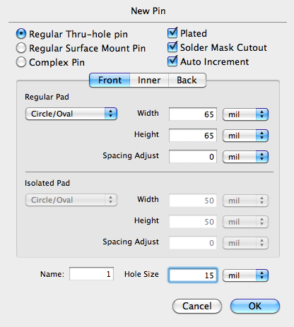
Double click on the New Pin tool in the tool palette to bring up the following dialog. The pins for our new part will be Regular Thru-hole pins which means they have circular pads 65 mils wide on all layers. Adjust the width and height fields in the Regular Pad area to 65 mils. Also, change the Hole Size to 15 mils. When we are done, the dialog should look like this:
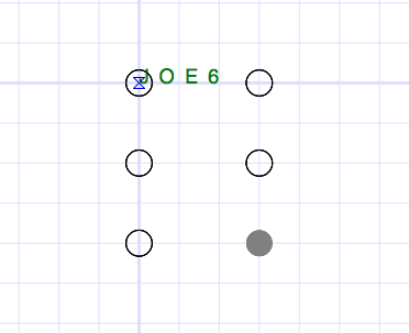
Using the newly configured New Pin tool, create a pattern of pins by clicking six times to produce the pattern shown below. If the pattern is not quite right, you can move the individual pins with the Select tool.
Making the Silkscreen
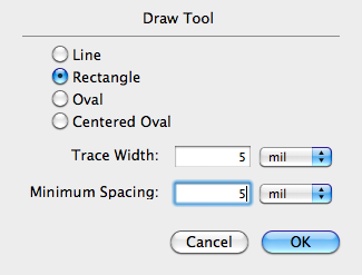
We will use the Draw tool to draw a silkscreen pattern around the pins on the silkscreen layer. Double click on the Draw tool in the tool palette to bring up the the dialog shown below. Change the draw option to Rectangle and the width to 5 mils as shown and press OK.
Now change the grid spacing to 25 mils using the Grid menu.
Change the current layer to the S1 layer (front silk) using the buttons at the lower left corner of the window.
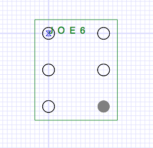
Now use the Draw tool to draw a rectangle around the pins so that it looks more or less like the following. The rectangle is created by clicking at one corner and dragging to the opposite corner. If you need to adjust the position of any of the line segments, you can do so with the Drag/Remove Pegs tool by clicking and dragging the endpoints of the segments.
When the silkscreen rectangle is finished, go back to the Front Layer.
Adjusting the Name Field
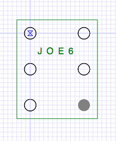
Well, the part name field is not really where we would like it, so we should move it. Click on the Select tool in the tool palette and move the part name so that it looks like this:
The part type is now complete. Click the OK button to dismiss the Edit Window and to place the new part type in the current library.
Using the New Part Type
Now that the JOE6 part type has been created, you can create instances of this part type like any other part.
Click on the New Part tool.
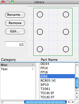
This makes the Library Parts window visible as shown below. You can click on the JOE6 item in the part list to see the part in the preview window.
Now clicking anywhere in the design area creates a new JOE6 part and places it at the click point. After two such clicks, you could see something like this:
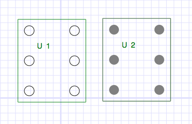
Notice that the part numbers are incremented automatically.
Making a Part Library
You can repeat the process to create other parts for your library. Once you have created parts and saved your design, you have also created a library. There is really no difference between a Library File and a Design File. Often, a Library file contains only part types and does not have any concrete instances of any part. However, this is not necessary. You can if you wish, use an existing Design file, containing part types, concrete parts, paths, etc., as a library for a new design.
All that you need to do is to Open the Library in a separate window. Then using the Library Parts window that you view via the Window menu, you can access any part type from any open design to create instances in your new design.