Starting a New Design
In this chapter we go through the process of creating a new design.
Background
To begin a new design, you should usually have three input files:
- Parts Library
- Parts List
- Net List
The Parts Library contains descriptions of every part type that you plan to use in your design. The format of the descriptions in the Parts Library is documented in the Osmond Reference Manual. The tutorial folder has an example Parts Library file (named Library) that you can examine at your leisure with an ordinary text editor.
The Parts List contains a list of every part in your design, including the part name and the part type. Each part should have a corresponding part type description in the Parts Library. The tutorial folder has an example Parts List (named PartList2) that looks like this:
Part RCR05 { Name R1 }
Part RCR05 { Name R2 }
Part RCR05 { Name R3 }
Part RCR05 { Name R4 }
Part DIP14 { Name U10 }
Part DIP14 { Name U11 }
Here we are dealing with a very simple design that contains just six parts: four resistors and two dual-inline packages. The words "Part" and "Name" are keywords. The part types used in this example are RCR05 and DIP14. The part names used are R1, R2, R3, R4, U10, and U11.
The Net List contains a list of all the signals in the design and what pins connect to each signal. The tutorial folder has an example Net List file (named NetList2) that looks like this:
Signal "Signal 1"
  { R2-1 R1-2 }
Signal "Signal 2"
  { R3-1 R2-2 }
Signal "Signal 3"
  { R4-1 R3-2 }
Signal "Signal 4"
  { U11-14 U10-2 }
Signal "Signal 5"
  { U11-13 U10-3 }
Signal "Signal 6"
  { U11-12 U10-4 }
Signal "Signal 7"
  { U11-11 U10-5 }
Signal "Signal 8"
  { U11-10 U10-6 }
Signal "Signal 9"
  { U11-9 U10-7 }
Signal "Signal 10"
  { U10-14 R4-2 U11-1 R1-1 }
The word "Signal" is a keyword followed by the name of the signal in quotes, followed by a list of pins that belong to this signal. Each pin is specified by a part name and pin name separated by a dash. Each part name should have a corresponding part in the Parts List.
Setup
With the Osmond application running, select the New command from the File Menu. This brings up a new window as well as the Design Options dialog shown below.
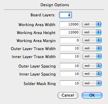
Since we have such a small design, change the Working Area Width and Working Area Height to 2000 mils. Also, change the Outer Layer Spacing and Inner Layer Spacing to 15 mils.
Using the Zoom View tool, magnify the view until the panel more than fills up the view.
Select the 50 mil command from the Grid menu to give us finer resolution.
Input
Now we need to read the input files. The first file we must read is the Parts Library.
Select the Import->Library... command from the File menu. Using the finder dialog, select the file named: Library from the tutorial folder.
Next we need to read the Parts List.
Next select the Import->Part List... command from the File menu. Using the finder, select the file named: PartList2 from the tutorial folder.
Finally, we need to read the Net List.
Select the Import->Net List... command from the File menu. Using the finder, select the file named: NetList2 from the tutorial folder.
Placement
From the Window menu, select the Show Deferred Parts command. This brings up a floating window containing a list of all the parts that have not yet been placed on the board. In our case this is all six parts. To place a part, click on the part in the part list. The part shows up as an image in the dialog display. Click and drag from the display to a location on the board. As you are dragging, a represantation of the part appears to assist you in positioning the part. Do this for each part until you have all the parts on the board. One possible final arrangement looks like this:
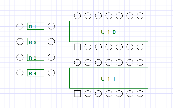
Once the Deferred Parts window is empty it can be safely closed. You can now proceed to connect all the pins and route all the paths using the methods learned in the earlier chapters.
Modifying the Design
Designs often need to be modified even after the net list is complete. If you change the net list file and import it again, Osmond tries to make the design consistent with the new net list, even if it has to remove paths in the process. If you would rather not modify the net list (or if you don’t have a net list at all), you can use Osmond tools to make changes or additions to the design directly.
Normally, the Choose/Connect Pins tool can connect pins only if they belong to the same net as defined in the net list.
However, if you hold down the Cmd key, you can connect any two pins by clicking on one pin and dragging to the other. This forces a connection between the two pins and makes both pins part of the same net. If neither pin belonged to a net before they were connected, a new net is created. If both pins belonged to different nets before they were connected, the two nets are merged into a single net.
It is possible to use this technique to define and construct all the connections of a design even without a separate net list file. For small to medium sized designs, the may be a viable option.
Normally, the Cut Path tool will remove a path between two pins, but the two pins still belong to the same net.
However, if you hold down the Cmd key while clicking on a path, the path is removed and the two pins are partitioned into two separate nets. One net contains the first pin along with everything connected to it, and the second net contains the second pin along with everything connected to it.
Experiment with using these tools to modify our example design by adding and removing connections.