Path Manipulation
This section lets you become familiar with tools for manipulating paths. a few keyboard functions, and with using some of the basic part manipulation tools in the tool palette.
Lesson 1 - Connecting Paths
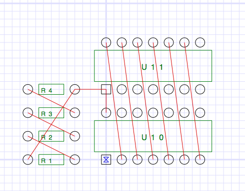
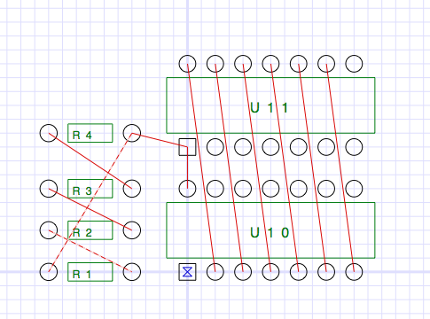
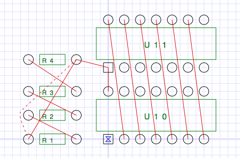
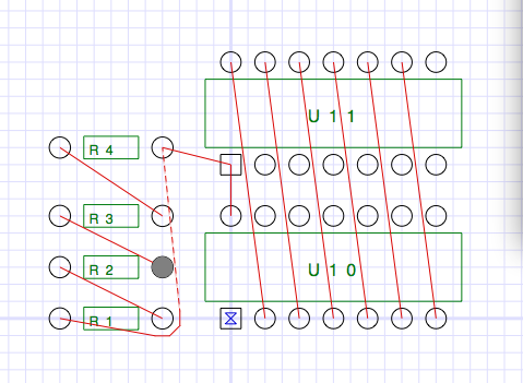
Open the Osmond document Sample2 in the usual way. This design contains four resistors and two dual inline packages but has no connecting paths, as shown below.

Because this design has a net list, the Osmond program knows what pins should be connected to what other pins. One way for you to see what pins need to be connected is to press the N key on the keyboard (N is for Next). The view should look like this:
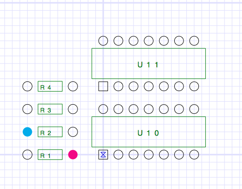
The two pins in color are the two pins that should be connected. Notice that the signal name (**Signal 1**) appears in the text area just below the tool palette.
To see the next set of pins that should be connected, press the N key again. Continue pressing the N key to cycle through all the signals that still need to be connected. To cycle through the signals in the reverse direction, press the V key on the keyboard (V is for preVious).
If you press the N or V keys continually and no pins are highlighted, this means that all the pins have been connected.
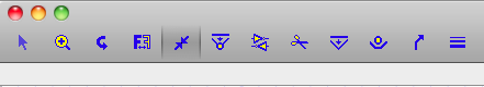
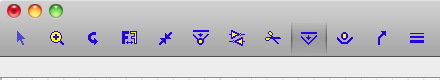
From the tool palette, select the Choose/Connect tool.
Click on any of the resistor pins. The pin that you click on changes color to cyan. Other pins that still need to be connected to this pin change color to magenta. If the pin you click on remains un-colored, then this pin should have no connection to any other pin.
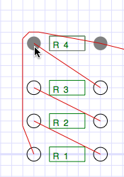
Now let us connect some pins. Click on the left pin of R4 (cyan) and drag toward the right pin of R3 (magenta). As you approach R3, a ghost line appears to indicate that this connection is allowable. When you release the drag, a new path is created.
Now click on the right pin of R4. Notice that you can connect this pin to any of three other pins. Click on the right pin of R4 and drag toward any of the three magenta colored pins. As you near the pin, a ghost line appears to indicate that the connection is allowed. Repeat the use of this tool until all four pins are connected.
From the tool palette, select the Cut Path tool.
Use this tool to delete one of tha paths you created by clicking on the path.
Experiment with connecting paths and cutting paths.
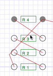
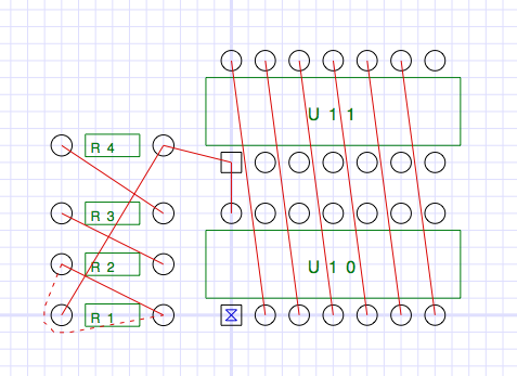
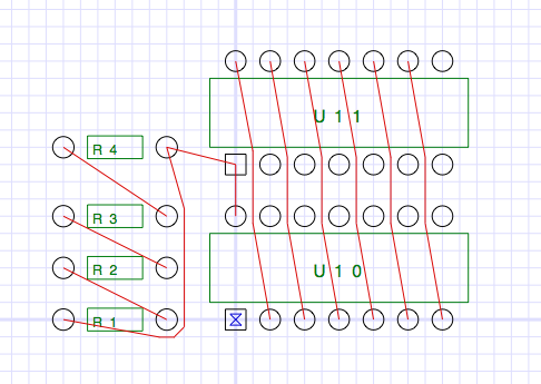
For the next lesson, connect all the pins so the design looks like this:
Lesson 2 - Moving Paths
From the previous lesson we have a design in which all the pins are connected. However, some of the paths cross and other paths get too close to some pins. The paths need to be adjusted or re-routed to fix these problems. In this lesson, we will examine several tools that we can use to re-route paths.
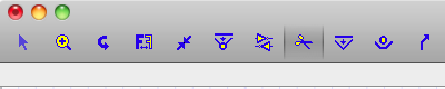
From the tool palette, select the Drag/Remove Pegs tool.
We can use this tool to stretch paths like a rubber band.
Use this tool to stretch the path from R1 to R4 in three steps as follows.
This is like stretching a rubber band around pegs in a peg board. Notice that a small mark appears on the peg nearest the cursor.
If you click directly on an existing peg, you can drag that peg and the associated path to a new location. If you click on the path between pegs, a new peg is created. The peg always snaps to the nearest grid crossing point.
To remove a peg, hold down the shift key while clicking on a peg.
Practice adding, dragging, and removing pegs until you feel comfortable with this tool.
For the next lesson, remove all the pegs you have added.
Lesson 3 - Wrapping Paths
Using just the Drag Pegs tool from the previous lesson, it is possible to completely route a PC board. However, that tool only adds pegs at grid crossings and pays no regard to any spacing requirements. We will now examine a more powerful tool that we can also use to route paths.
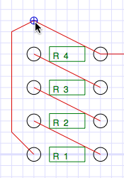
From the tool palette, select the Wrap Paths tool.
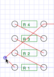
Click and drag the path from R1 to R4 upward and to the left over the left pad of R4 like this:
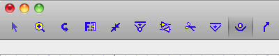
The tool ensures that there is adequate spacing between the path and the pad. To finish routing this path, click and drag the path to the left of the left hand pad of R2 like this:
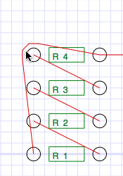
From the tool palette, select the Select/Move tool. Use this tool to move R4 up one grid interval like this:
Notice that the path that was "wrapped" around the left pad of R4 is still wrapped even though R4 was moved.
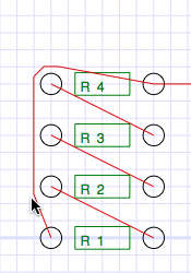
Reselect the Wrap Path tool from the tool palette.
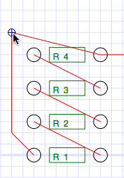
You can usually unwrap a "wrapped" path by clicking on the path near the wrap and dragging in the opposite direction. Try this with the section of path around the left pad of R4. If you do this correctly, you will see this:
Another way to unwrap a path is to simply remove the pegs one at a time using the Drag/Remove Pegs tool that we learned about in the previous lesson.
Practice wrapping and unwrapping paths around various pads until you are comfortable with this tool.
For the next lesson, remove all the pegs that you have added.
Lesson 4 - Automatic and Semi-Automatic Routing
From the Design menu, select the Check Current Layer command. This command checks the current layer for conflicts caused by crossing paths or inadequate spacing. When it finds a conflict, it puts up the following floating dialog and highlights the conflict as shown.
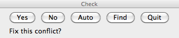
Click on the Yes button. The program now proposes a solution to this conflict for your approval.
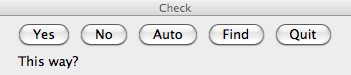
Click on the No button. The program now proposes a different solution to this conflict.
Click on the No button again until you get this solution.
Click on the Yes button. The program implements the solution and finds the next conflict.
You can continue in this manner, finding and resolving conflicts one at a time, until the board is completely routed. Because this design is so simple, however, we can let the program do more of the work.
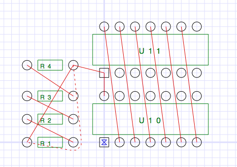
Click on the Auto button. This tells the program to find and resolve all conflicts automatically, without user input, using its own simple heuristics to decide between alternate solutions. This produces the finished product below:
The Auto button should be used with caution. The heuristics that the program uses to decide between alternate solutions are very simple minded and may not jibe with good judgment. Also, it is possible for the program to fall into an infinite loop if the solution to conflict A creates conflict B and the solution to conflict B brings us back to conflict A. If the program appears to be waffling between two solutions, you should break out of Auto mode by pressing any Cancel button at the lower left.
Since we will be working with this same file in the next chapter, you should close the design without saving.