Edit Menu
Undo
The Undo command reverses the most recent operation including all side-effects that resulted from that operation. When the Undo command is invoked, the Redo command is enabled to allow you to undo the Undo command.
Redo
The Redo command reverses the most recent Undo operation, including all side-effects that resulted from that operation.
Cut
The Cut command deletes all selected parts (if possible) and freehand paths and places them in the clipboard. Parts that have connecting paths cannot be cut; you need to remove the connecting paths first. Parts and freehand paths in the clipboard can then be pasted into this or any other design with the Paste command.
Copy
The Copy command places a copy of all selected parts and freehand paths into the clipboard. Parts and freehand paths in the clipboard can then be pasted into this or any other design with the Paste command.
Paste
The Paste command places all parts and freehand paths that are in the clipboard into the current design. The location and orientation of the parts and freehand paths are the same as they were when the part or freehand path was cut or copied originally. Freehand paths are always pasted into the current layer of the design even if they were on a different layer when they were originally cut or copied.
Delete
The Delete command is used to delete all selected parts (if possible) and freehand paths. Unlike the Cut command, deleted objects are not placed in the clipboard.
Select All
The Select All command selects all entities of the current design. Once selected, these parts and freehand paths can then be moved as a unit, copied to the clipboard, or otherwise manipulated.
Duplicate
The Duplicate command duplicates selected parts or selected freehand paths. The first item duplicated is placed below and to the right of the original. However, if you move this first duplicate relative to the original, then the second duplicate will be placed in the same position relative to the first duplicate, the third duplicate will be placed in same position relative to the second duplicate, and so on.
Select Sub Design…
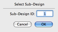
The Select Sub Design… command lets you select a particular sub-design, which is a design that has been imported into the current design with the Import → Sub Design… command. When sub designs are imported, they are given sequential numbers, starting with 1. This command brings up the dialog shown below, allowing you to select a particular sub-design by specifying its sequence number. Once selected, the sub-design can be moved as a unit.
Move Selected…
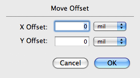
The Move Selected… command lets you move all selected objects by a specified amount. This command brings up the dialog below that lets you specify the relative movement in mils or millimeters in both the X and Y direction.
Design Rules…
The Design Options… command brings up the dialog below to permit you to change options or characteristics of your design.
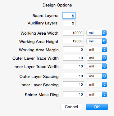
The Board Layers text field lets you specify the number of layers your PC board design should have. This number is the actual number of signal layers and does not include other layers such as silkscreen layers, solder-mask layers, or auxiliary layers.
The Working Area Width and Working Area Height text fields let you specify the horizontal and vertical size of your working area. This is not necessarily the same size as your PC board but should be at least as large as your board.
The Working Area Margin text field lets you specify the width of a margin area around your working area. This margin area can be used to keep parts temporarily before you place them on the board.
The Default Trace Width text fields let you independently specify the default width of signal paths for both outer and inner layers.
The Default Spacing text fields let you independently specify the default spacing of signal paths for both outer and inner layers.
The Solder Mask Ring text field lets you specify how much larger the solder mask pads are compared to the pads they enclose. A value of 10 mils, for example, will result in a solder mask pad that is 10 mils larger than the enclosed pad in every direction. Note that all the measurements can be specified in either millimeters or mils.
Gerber File Names…
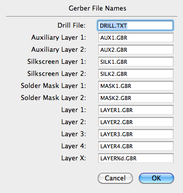
The Gerber File Names… command brings up the dialog below to allow you to modify the names given to Gerber and Drill files. For boards having four signal layers or fewer, you can specify the name of each file individually. For boards having more than four signal layers, the last item lets you specify the format of the file name, similar to the way strings are formatted in a printf statement in C. In the default case, the %d is replaced by the layer number.
PDF Image…
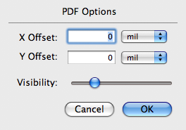
The PDF Image… command brings up the dialog below to allow you to adjust the offset and the visibility of the background PDF image that was imported with the Import → PDF File… command.
Colors…
The Colors… command brings up the dialog below to allow you to change the color of various display elements.
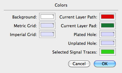
You can change the background color, the colors used for both metric and imperial grids, the colors used for plated and unplated holes, the colors used for the paths and pads on the current layer, and the color used to highlight all the traces of the selected signal. To change pad and path colors on other layers, just go to the layer and issue this command again.
Units…
The Units… command brings up the dialog below to allow you to change the units used in dialogs and on the information field.
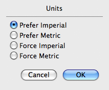
If Prefer Imperial is selected, then measurements will be expressed in mils unless the measurement is more naturally expressed in millimeters. If Prefer Metric is selected, then measurements will be expressed in millimeters unless the measurement is more naturally expressed in mils. If Force Imperial is selected, then measurements will always be expressed in mils. If Force Metric is selected, measurements will always be expressed in millimeters.