Parts Menu
Find Part…
The Find Part… command lets you find a part in your design. A dialog appears as shown in below.
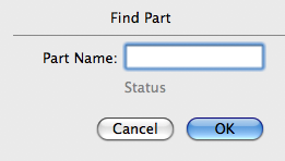
When you enter the part name and press OK, the part is selected and centered in the view. If the part is not found, the Status text changes to tell you that the part is not found. The Status text also changes to tell you if the part is in the deferred lise.
Lock
The Lock command locks all selected parts. Locked parts cannot be moved, flipped, or rotated.
Unlock
The Unlock command unlocks all selected parts. Once a part is unlocked, it can be moved, flipped, and rotated.
Defer
The Defer command moves all selected parts that have no connections to the deferred list. You can see a list of the deferred parts by opening the Deferred Parts window from the Window menu.
Update All Parts
The Update All Parts command scans the part list and updates those parts that do not yet have a part type defined. It also updates those parts that have had their part type modified.
If you have imported a part list that has parts whose part types are not in an open library, you can use this command to update these parts after the part type is made available. A part type can be made available either by importing a library that contains the part type, opening a file that contains the part type, or by creating the part type in the part type editor with the Make New Part Type… command in the Parts menu.
Group Selected
The Group Selected command groups all selected parts such that the group can be manipulated (selected, moved, rotated, flipped) as a single entity. Once a group is created, it can be combined with other parts or groups into a larger group to any level of nesting.
Un-Group Selected
The Un-Group Selected command finds all groups in the selected parts and separates them into their individual elements, which may be individual parts or lower level groups.
Align
Align → Horizontally
Align → Vertically
The Align → Horizontally and Align → Vertically commands align selected parts horizontally or vertically, respectively, with respect to their origins. If one of the parts is locked, the unlocked parts will be moved to align with the locked part. If none of the parts is locked, parts will be aligned with the part nearest the top of the screen (for Align → Horizontally) or the left most part (for Align → Vertically). If several parts are locked, the unlocked parts will be aligned with the locked part nearest the top of the screen (for Align → Horizontally) or the left most locked part (for Align → Vertically). In no case will locked parts be moved.
Align → Left Pins
Align → Right Pins
Align → Top Pins
Align → Bottom Pins
These commands align the selected parts horizontally or vertically, with respect to their left-most, right-most, top-most, or bottom-most pins, respectively. If one of the parts is locked, the unlocked parts will be moved to align with the locked part. If none of the parts is locked, parts will be aligned with the part nearest the top of the screen (for Align Left or Right) or the left most part (for Align Top or Bottom). If several parts are locked, the unlocked parts will be aligned with the locked part that is nearest the top of the screen (for Align Left or Right) or the left most locked part (for Align Top or Bottom). In no case will locked parts be moved.
Align Name
Left
Center
Right
These commands align the name field of all selected parts within the part itself. For example, the Align Name → Left command moves the name field of the part to the left edge of the part's silkscreen. The command Align Name → Center, which immediately follows, moves the name field so that it is centered horizontally with respect to the silkscreen. Similarly for the the Align Name → Right command.
Top
Center
Bottom
These three commands work in a similar manner, only moving the name vertically instead of horizontally.
Calculations are performed using the left-most, right-most, top-most, and bottom-most points of the silkscreen. If a part has no silkscreen, this command has no effect.
Align Value
Left
Center
Right
These commands align the value field of all selected parts within the part itself. For example, the Align Value → Left command moves the value field of the part to the left edge of the part's silkscreen. The command Align Value → Center, which immediately follows, moves the value field so that it is centered horizontally with respect to the silkscreen. Similarly for the the Align Value → Right command.
Top
Center
Bottom
These three commands work in a similar manner, only moving the value vertically instead of horizontally.
Calculations are performed using the left-most, right-most, top-most, and bottom-most points of the silkscreen. If a part has no silkscreen, this command has no effect.
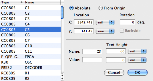
Part Attributes…
This command brings up a dialog as shown in below that lets you view and modify part attributes such as location, orientation, name, and value. A list of all selected parts is shown on the left. As you click on each item on the list, the associated attributes are shown on the right. You may modify any of the attribute for each part. When you are satisfied, hit OK to apply all the changes. If you hit Cancel, none of the changes will be made.
Replace Parts…
This command lets you replace each of the currently selected parts with a different part type.
The dialog is shown in below. The dialog has two scrolling lists. The first list shows all the selected parts, including the part type and the part name. The second expandable list can be used to navigate to any part of any library or open design.
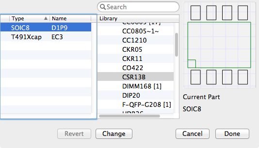
To replace a part, select a part in the first list, then click on the desired replacement part type in the second list, and then click on the Change button. The part type field in the first list is updated and each changed entry is indicated by a star at the leftmost column. You will notice as you click on either the part in the first list or the part type in the second list, that a small preview of the part or part type is drawn at the right.
A search field allows you to filter the part type names displayed to only those that contain the text string that you enter in the search field. This can greatly simplify your search for the correct part type.
If a part has been changed, you can select the part and press the Revert button to restore it to it's original part type.
Once you are satisfied with all the changes, you can finalize the command by clicking the Done button. Clicking the Cancel button will leave all the parts unchanged.
Edit Parts…
This command lets you edit each of the currently selected parts in a new window. For each part selected, a special editing window appears as shown below.
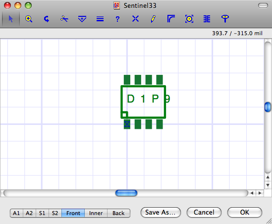
A special subset of the usual toolbox tools is at the top of the window. Tools that are not really applicable to part editing are not included. In addition, the buttons, Save as…, Cancel and OK, appear at the bottom of the window. The selected part appears centered in the window. However, this part has been dis-assembled such that each pin is now an independent part and each path is now an independent path. You can, therefore, completely change the part using many of the normal toolbox tools.
-

- To change the position of a pin, use the Select tool. You can also use this tool to change the position of the Part Name or the Part Value.
-

- To change the silkscreen path, go to the Front Silk layer and use the Drag tool.
-

- If you wish to add a new path to any layer, use the Draw Freehand Path tool. Make sure you first go to the correct layer.
-
- To change the pin name, select the pin with the Select tool and then use the Part Attributes… command from the Parts menu.
-

- The origin of the part is specified by the Grid Origin. Therefore, if you wish to change the origin of the part, change it using the Origin tool.
-

- To change the pad-stack of a pin, use the Change Pin/Padstack tool.
-

- To add pins, use the New Pin tool.
-
- To delete a pin, select it with the Select tool and then delete it with the delete button on the keyboard or the Cut command in the Edit menu.
You can get more information on all the available tools in the Tools and More Tools sections of this document.
Once you are satisfied with the changes you have made, press the OK button. The part being edited is automatically re-assembled and the original selected part is replaced with this new part. You can also press the Cancel button to leave your original part unchanged.
If you press the Save As… button, a dialog appears as shown below that lets you define the name of a new part type to add to the library. You can also specify the size of the name and value text associated with this part that will appear on the silkscreen layer. If you do not want the name or value to appear on the silkscreen layer, make the corresponding size zero.
Selected to Pad Outline…
This command creates a new pad type in your library by defining the outline of the pad using a closed path that you produce using the Freehand Draw tool along with other path editing tools such the Move Peg tool. A dialog appears that allows you to specify the name of the new pad type. This name then becomes available to other tools, such as the New Pin tool, that are used to create new part types.
Before using this command, first produce a closed path (where the end point meets the starting point) anywhere in your design using the Freehand Drawing tool. You can probably get a good start if you configure the Freehand Drawing tool to produce a rectangle or an oval. Next, perform whatever modifications are needed to the path using the Move Peg tool or other tools such as the Curve Tool. The outline of the new pad is defined by the vertices of the closed path so the path width and spacing do not matter.
Next, use the Origin Tool to specify the origin of the pad within the closed path. The origin of the pad is where connecting traces will tie and where holes (if needed) will be located. The pad origin does not need to be at the center of the pad but it does need to be within the pad outline. You may need to adjust the grid spacing to ensure that the origin is positioned correctly.
Finally, use the Select tool to select the closed path and issue the Selected to Pad Outline command from the Parts menu. A dialog appears that asks for the name of the new pad type. You will get an error message if the path is not closed, or if the origin is not within the pad outline, or if the path has more than 50 vertices.
Once a new pad type has been created, its name will be available to other tools, such as the New Pin tool, that make use of pad types. For example, when you double-click the New Pin tool, the pop-up that lets you specify the pad type will now contain the name of the new pad type that you have created. You can now delete the original path used to define the pad outline since it is no longer needed.
If a pad created using this method is embedded in a copper flood area, then the clearance for the pad will be provided by a rectangular area that has been sized to ensure that the entire pad has at least the specified clearance to the copper flood area.
Save Selected to Library…
This command creates a new part type in your library by combining all the features in all the selected parts and freehand paths into a single entity. A dialog appears that allows you to specify the name of this new part type.
If the grid origin has been placed on a pin of one of the selected parts, or on a vertex of one of the seletecd freehand paths, then this specifies the origin of the new part type. Otherwise, the origin of the new part type is set to the lower left hand corner of the assembly of features.
This command permits an alternative method of creating new part types since they can be built in the main design window without using a separate part type edit window. Of course, if an existing part type needs to be modified, then the part type edit window is required.
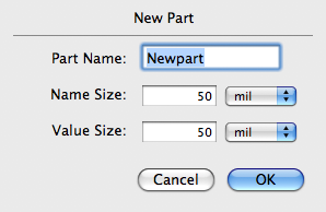
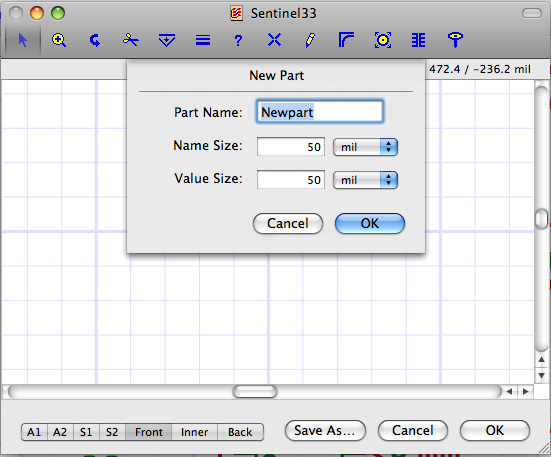
Make New Part Type…
This command lets you create a new part type in a new window and add it to the current library. When you invoke this command, a window appears as shown below with a dialog asking for the name of the new part type, the size of the Name text, and the size of the Value text. The Name and Value text normally appear on the silkscreen layer. If you do not wish the Name or Value text to appear, make the corresponding height zero.
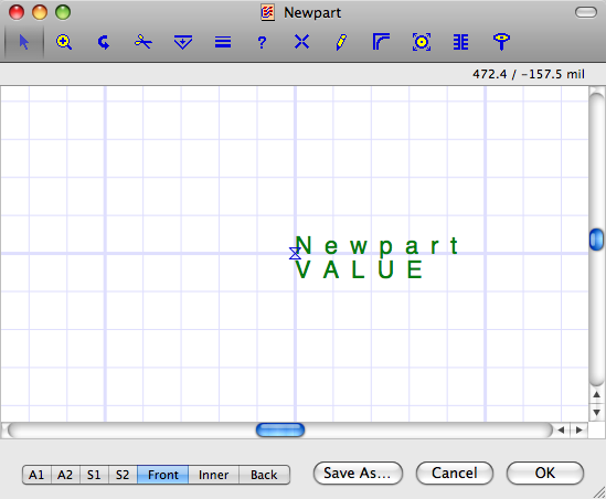
The resulting new part edit window is shown below. The grid origin, which corresponds with the origin of the part, is placed at the center of the window. The name field is also placed at the center. If a non-zero Value Height is specified, the value appears below the Name.
A subset of the normal toolbox tools is at the top of the window. Use these tools to create your new part. You will likely make extensive use of the New Pin tool, the Draw Freehand Path tool, and the Select/Move tool. See the Edit Parts… command above for a description of each of these tools.
When you have finished designing your part, click the OK button. This adds the part to the current library. Once the part is in the library, you can add instances of this part to your design by dragging it from the Library Window or by using the New Part tool.
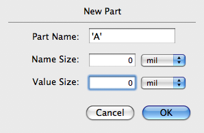
Text Characters
You can use the Make New Part Type… command to create or modify the default text characters that are used with the Text tool and that are used when creating Gerber text in the Silkscreen layers.
Text characters are similar to other part types but are treated in a special way by the Osmond system. To allow Osmond to recognize a character part, it is named a special way. For example, the character A is named: 'A'. That is, a single quote followed by the letter itself followed by a single quote.
Since text can be any size, Osmond can scale the character parts by any amount as needed. To simplify the scaling, Osmond assumes (for purely historical reasons) that the height of each character, as it is defined in the library, is 14 mils tall and that the origin of the character is as described below. Newly defined characters, therefore, should remain consistent with these assumptions.
To make a character A, for example, issue the Make New Part Type… command and fill in the fields as shown below.
When the Part Edit window appears, change the grid size to 1 mil and zoom in until the grid is visible. Using the Draw Freehand tool, draw the character as you wish and click OK when done. You will probably need to change the width of the Freehand tool to 2 mils or less. A view of the character A as it is defined in the library is shown below.
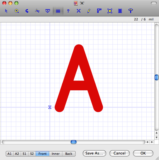
Notice that the left edge of the character (including stroke width) is 1 mil to the right of the origin, the bottom of the character is 1 mil below the origin, the top of the character is 13 mils above the origin, and the width of the character is 10 mils. New characters should be consistent with these dimensions to work well with existing characters. Existing characters use a stroke width of 2 mils but you should be able to use any stroke width you choose.