View Menu
Actual Size
The Actual Size command scales the view so that all items on the display are at their actual size, assuming a standard display of 72 dots per inch.
Double Size
The Double Size command scales the view so that all items on the display are at twice their actual size, assuming a standard display of 72 dots per inch.
Full View
The Full View command scales the view so that the entire design panel is visible.
Zoom In
The Zoom In command magnifies the view by an amount equal to the current zoom factor. The center of the view is kept at the center. To change the current zoom factor, double-click the Zoom Tool.
Zoom Out
The Zoom Out command de-magnifies the view by an amount equal to the current zoom factor. The center of the view is kept at the center. To change the current zoom factor, double-click the Zoom Tool.
Full Width Traces
The Full Width Traces command lets you toggle between displaying all paths at their full width, and displaying only the center line of all paths.
Solid Pads
The Solid Pads command lets you toggle between displaying all pads as an outline, and displaying pads filled in with color. The color can be changed with the Colors… command in the Edit menu.
Trace Outlines Only
The Trace Outlines Only command lets you toggle between displaying only the outlines of paths, and displaying the paths completely filled in. This is apparent only when the paths are shown at their full width (see Full Width Traces command above).
Show Holes
The Show Holes command lets you toggle between displaying or not displaying holes in the board. The color used to show holes can be changed with the Colors… command in the Edit menu.
Show Names
The Show Names command lets you toggle between showing or not showing part name text on the display. If part name text is shown, it is also generated when printing and when producing Gerber and PostScript files. If part name text is not shown, it is not generated when printing or when producing Gerber or PostScript files.
Show Values
The Show Values command lets you toggle between showing or not showing part value text on the display. If part value text is shown, it is also generated when printing and when producing Gerber and PostScript files. If part value text is not shown, it is not generated when printing or when producing Gerber or PostScript files.
Show Pin Names
The Show Pin Names command lets you toggle between showing or not showing pin names on the display near each pin. This is for reference only. Pin names are not generated when producing Gerber or PostScript files.
Show Part Origin
The Show Part Origin command lets you toggle between showing or not showing a small target located at the origin of each part. When this target is shown, it can be used as a handle to move, rotate, or flip the part using the appropriate tools.
Show Selected Signal
The Show Selected Signal command lets you toggle between highlighting or not highlighting all the traces that belong to the currently selected signal. Note that all the traces on all layers belonging to the signal are highlighted, even if the layer is otherwise not visible.
Vector Text
Historically, part names and part values are shown on screen using system fonts. However, when Gerber files or Postscript files are generated, part names and part values are made with the vector fonts that are defined in the parts library. This means that the text that you see on the screen is only an approximation of the text that appears on the board.
When Vector Text is selected, the vector fonts in the parts library are used to display the part names and part values on the screen. This way, what you see on the screen should match exactly what appears on the board. Of course, this works only if the vector fonts already exist in the parts library.
Layers Visible…
The Layers Visible… command brings up a dialog like that shown below that lets you specify which layers are always visible. In the Osmond system, the current layer is always visible. This dialog lets you select which layers, along with the current layer, are also always visible. By default, the front and back silkscreen layers and the front and back auxiliary layers are always visible.
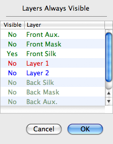
The colors used for the layer names reflect the color of the paths on the given layer. These colors can be changed with the Colors… command in the Edit menu.
The Visible column indicates which layers are always visible. Click on the layer name to toggle the visibility. You can also toggle the visibility of a signal layer by pressing the layer number on the keyboard while holding down the option key.